Vessel Stability measures the ship’s uprightness or how it remains at water level. Now, in a broad sense, this uprightness can be conceived from two perspectives, and ship stability can be described in two ways: i) longitudinal and ii) Transverse stability.
Transverse stability is the vessel’s tendency to remain upright when viewed in a longitudinal direction or when looking at the vessel from its fore or aft. Thus, we look at the vessel’s cross-section or faceward view.
Now, when the vessel inclines towards its port or starboard side about its longitudinal axis or, in technical terms, the ship’s centreline, we say that the vessel has lost its uprightness. When a vessel inclines towards the starboard, there is more draft on the starboard side than on the port and when the vessel leans towards the port side, vice-versa.
We have also studied the several facets of transverse stability, including the disturbing forces responsible for this loss in uprightness, heel and list (remember the difference?), myriad technical terms associated with this problem like the centre of buoyancy, the centre of gravity, metacentre, metacentric height, righting arm, and so on. Moreover, we have also learnt about the inclining experiment and how to attain stability.
Let us briefly look at another aspect of ship stability.
SHIP TRIM AND A BRIEF ON LONGITUDINAL STABILITY
Longitudinal stability is the measure of a vessel’s uprightness’ when we describe it from a lateral or sideways sense. That is, looking at the vessel’s length from any side. Here uprightness is defined as the vessel’s state of remaining level or even with the waterline throughout its length or span.
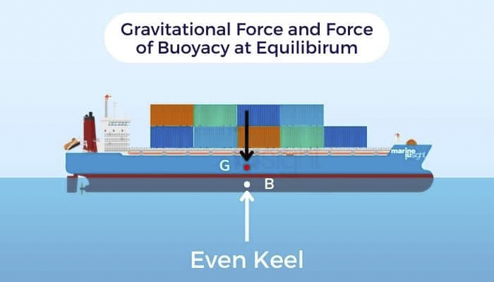
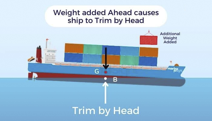
Now consider a situation when this state is lost, the vessel inclines towards the fore or aft by bow or stern respectively, and the even waterline changes. This is known as the ship’s trim. In other words, when the draft or water level is different or variable throughout the vessel’s length, the vessel is said to be trimmed.
When the draft or water level is higher at the bow or forward as compared to the stern or aft, the vessel is said to have a trim by bow or trim by forward. Conversely, when the draft is higher at the stern or the aft of the vessel compared to the bow end, the vessel is said to have a trim by aft or trim by stern.
The causes for this disparity in the drafts in a longitudinal sense of a vessel can be various factors more or less similar to the ones in the case of transverse stability, i.e., external like weather or sea conditions or internal like loading or weight shifts.
Measuring Trim
Trim measurement is very important for both designers and vessel operators. In simple terms, the mathematical difference between the forward and aft drafts, measured at the extreme ends of the vessel, is the Trim. Suppose the vessel has a draft TF measured at the forward end and a draft value TA measured at the aft end. The net trim of the vessel is the difference: +/- (TF – TA ).
Trim angle is also important while studying trim. A vessel has differential submergence at forward and aft, and throughout its length, the waterline changes as expected. Assuming the waterlines to be straight lines and ignoring effects like waves, ripples, etc., for basic calculation purposes, the previous and the new waterlines intersect at a certain point in the vessel’s length.
The equal and opposite angles subtended at the point of intersection are known as the trim angle. By the simple laws of geometry, this is directly proportional to the extent of trim faced by the vessel at a given time.
Physics of Trim and A Brief on Longitudinal Stability
Now trim is caused due to a force and an associated moment, whether external or internal. So, from the point of view of physics, this force and moment need to act somewhere to bring about the desired effect of trim.
They essentially act about a transverse axis passing through the point where the original and new waterlines intersect, as described in the last section. This point is known as the centre of flotation, or F.
This point is also the geometric centroid of the vessel’s water plane at the given time. Suppose some weight is added at a point lying on the same vertical line as the centre of flotation. In that case, there won’t be any change in the net trim, but only sinkage as from the physics of bodies, any kind of force acting on the centroid does bring about any change in the resultant moment, which effectively remains zero. Forces and loads acting anywhere else results in effective trimming moments acting about F that can cause changes in the trim.

The terms associated with longitudinal stability are more or less similar to that of the transverse. While the point keel K, and the centre of gravity, G, remain the same in a vertical sense, the centre of buoyancy, B, and the Metacentre, M, are taken as longitudinal.
The distance from the keel to the metacentre, KM, is once again the sum total of the distance between the keel and centre of buoyancy, KB, and the metacentric radius, BM, which is also the vertical distance between the centre of buoyancy and the Metacentre, M, or the sum total of the distance between the keel and the centre of gravity, KG, and the metacentric height, GM (distance between G and the M ), all quantities being analogous to those being discussed concerning transverse stability.
However, as already mentioned, specific measures like KM, GM, and BM are relevant from the point of view of longitudinal stability. They are marked with a subscript L while denoting for all practical purposes. We will not go into the detailed aspects of these and their associated calculations and derivations, which are beyond the scope of this article, which is mainly for understanding trim and longitudinal stability.
However, one very important quantity in our discussion that needs to be discussed is the moment to cause trim or MCT.
As we have already discussed, trim is always related to some enacting moment. So, for a given trim, t, there needs to be a certain moment associated with it. In the simplest of cases, when there is a shift in some weight, w, from one point to another over a certain distance, h, the moment is simply the product, w x h.
Similarly, when there is a change in internal loading, say, for instance, some kind of weight being added at a certain location, the moment can be likewise considered the product of the added weight w’, and the distance, say l, from the given point to the centre of flotation, F.
However, the scenario is different for external causes bringing about trim, though there are classifications and other empirical relations for the determination of the forces and moments due to these, like in transverse stability.
But for convenience, the moment to cause trim, which is a determiner of the ease or the minimum effort required to cause the trim has been standardised. Now the question arises: standardised to what? The answer is standardised to cause unit trim. Now carefully note the last term.
This means that given the disposition of a vessel, the minimum moment to cause this unit trim can be determined from physical relation. This is given as W X GML / L, where W is the displacement, GML is the longitudinal metacentric height, and L is the vessel’s length. We do not go into the derivation of this relation and its implications in calculations.
Now, this term unit trim can be ambiguous. The above relation essentially gives the moment to cause a trim by 1 metre. If we want to get the moment to cause a trim of just 1 cm, we simply divide the above quantity by 100. This has been further standardised as MCT1cm. Similarly, for getting in other units like feet or inches, the above relation can be transformed accordingly, though centimetres and metres are the two most common units of today.
MCT is also useful for estimating the drafts at which the vessel is likely to float at given conditions of loading.
Similarly, sometimes under certain conditions, trimming by bow is also important. Other than efficiency, trimming under certain limits is also crucial for instances like weather, sea-states, and other ballasting requirement issues. Several modern ship operators are purposefully using this useful trim to not only optimise efficiency but also save on energy consumption and even reduce emissions. The best trim for a vessel at a given time is determined by optimising all conditions of speed, draft, external conditions, and design.
Source: Marine Insight